This plugin is designed to analyze the spectral images by phasor approach. Download the package and extract the zip file in the ImageJ plugin folder : “X:\Program Files\ImageJ\plugins folder”. X is the drive where the ImageJ is installed. Then Download the sample images.
spectral_phasor.zip image-dapi-bodipy-texas_red.zip
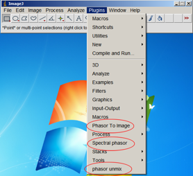
If you restart ImageJ in the Plugins menu three “Phasor to image” and “Spectral phasor” and “phasor unmix”will be added.
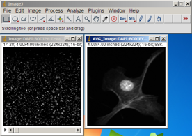
To start, from File menu open the “Image-DAPI-BODIPY-Texas red.tif” This is a cell stained with DAPI (DNA), Bodipy (tubulin) and Texas Red (actin). From Image menu choose Stacks>Z Project… Then from Projection Type choose Average Intensity. The Image should looks like this:
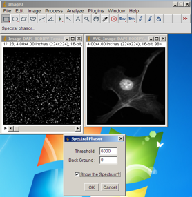
Now select the stack image again and from Plugins menu select Spectral phasor.
In Threshold textbox enter “6000” and select the “Show the Spectrum”.
In “Threshold” text box, as the name imply you can enter the value for thresholding the pixels to remove them from analysis. By entering “6000” we make sure that we have removed the background signal.
“Background” is the value to be subtracted from the pixels value.
Now press the OK button.
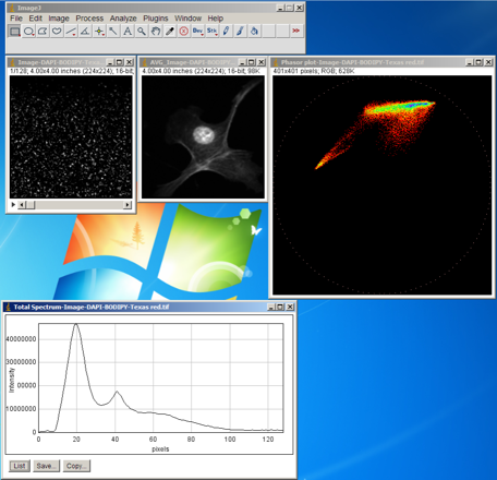
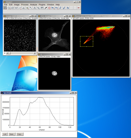
The total spectrum and the phasor cloud will be shown. we can do some basic segmentation based on the position of the phasor points. From ImageJ toolbar select the “Rectangular” and select a region of intersst on the phasor plot as shown in the figure below. Then from Plugins menu select the Phasor To Image. The corresponding pixels and the spectrum will be shown.This confirm the position dependancy of phasor plot on the spectrum.
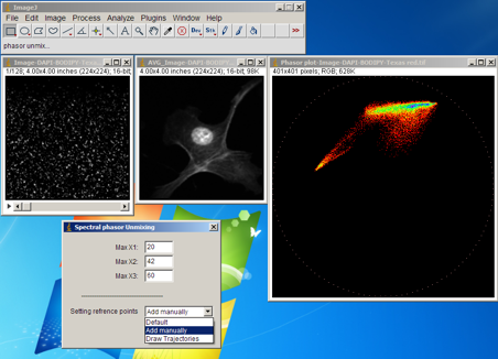
Click on a point on the phasor plot to deselect the region of interest. Now from Plugins menu select Phasor unmix.
In the Max X1, Max X2 and Max X3 you can enter the peak positions for the pure components that you expect are present in the image. In the ComboBox there are three options: If you select the Default the unmixing is performed based on the previous settings for the reference points which is saved automatically on hard disk. If you select Add manually the trajectories will be shown based on the numbers entered on the Max X1, Max X2 and Max X3 fields. These trajectories are drawn by changing the width of a Gaussian spectrum.
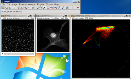
Now enter 20,42 and 60 for the Max X1, Max X2 and Max X3, select Add manually and press OK. The trajectories are drawn. The reference points can now be estimated by extrapolating the phasor clouds to the three reference curves.
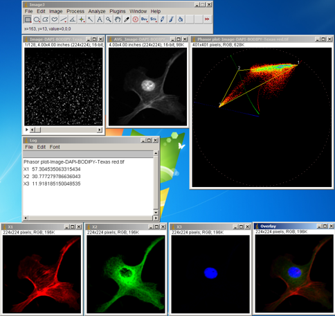
Select the reference point by clicking on the phasor plot as shown in figure below.A very clear segmentation with minimal bleeding through is achieved. The overlay RGB image and the fractional intensities are also shown.
Citation:
Farzad Fereidouni, Arjen N. Bader, and Hans C. Gerritsen, “Spectral phasor analysis allows rapid and reliable unmixing of fluorescence microscopy spectral images,“ Opt. Express 20, 12729-12741 (2012)
Authors:
                   Farzad Fereidouni Farzad.feraidounie@gmail.com
                   Gerhard Blab
