−Table of Contents
Digital Darkfield Decomposition
Introduction
Digital-darkfield analysis involves the spatial mapping of selected frequencies across a digitized image, much as analog (e.g. electron-optical) darkfield-imaging allows one to locate crystals responsible for a given diffraction spot. This analysis involves a type of image decomposition which, like wavelets, is intermediate between direct and reciprocal (spatial-frequency) space [1].
Digital-darkfield analysis is of particular use on images that have well defined spatial-frequencies in them, like lattice-fringe images of atomic-planes encountered edge-on by high-energy electrons in crystalline materials [2-10].
More soon on the sections below. In the meantime, here are some links* on this subject plus some other electron microscope image-analysis strategies.
Author
P. Fraundorf, Department of Physics & Astronomy and Center for NanoScience, University of Missouri in St. Louis.
Features
A set of java plugins is provided for this work, along with ImageJ macros for putting them to use. The java plugins include routines for quantitatively converting complex-number arrays to and from RGB images with pixel-intensity proportional to coefficient log-amplitude and pixel-hue linked to coefficient phase. These plugins may also be used by hue-maximization routines, to be described elsewhere.
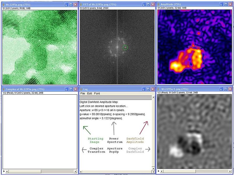
Some of the routines allow the user to place a circular aperture in the power spectrum of an image, from which periodicity amplitude and phase-gradient (strain) maps are calculated, labeled, and displayed. The periodicity-amplitude map is shown (top right panel) in the figure below, for one of the many periodicities which show up in the power spectrum (top center panel) of the HR-TEM (electron phase-contrast) image of some WC1-x nanocrystals [11] (top left panel).
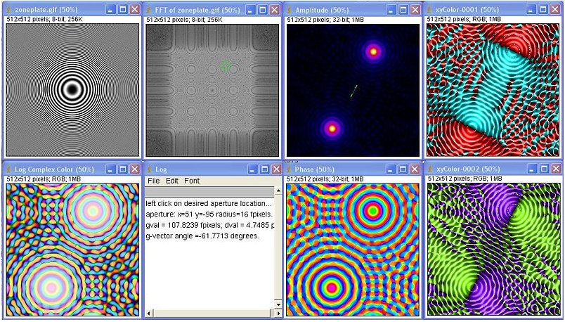
The composite below here shows a log complex-color darkfield (bottom left panel), and log component-color analyses (right-most panels) of isotropic and shear periodicity gradients in a zone-plate calibration image. In the latter, red intensity denotes compression, cyan denotes tension, indigo denotes counter-clockwise twist, and chartreuse denotes clockwise twist.
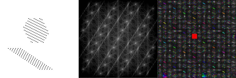
Another set of routines allows the user to tile frequency space with an array of tiny darkfield (plus one brightfield) images, yielding a tableau which contains one direct-space image formed by the spatial-periodicities found in each of the frequency-space tiles. This darkfield-tableau strategy has applications in finding patterns (like icosahedral-twin “bow-ties” and “butterflies”) in a lattice image of a collection of randomly-oriented periodic objects [12-13].
For example in the figure below, the tableau (right panel) can be used to identify which diffraction features (center panel) come from which 2D lattice structures (left panel). One can also check this because the diffraction spots are convolved by the lattice shape transform, which is elongate along directions in which the corresponding lattice is narrow.
Description
Images ψ[x,y] drawn from only a subset of spatial frequencies in an input image s[x,y] may be obtained by construction of a Fourier-space window-function W[fx,fy] with which to multiply the input array's Fourier transform S[fx,fy]. Inverse transforming this product yields a direct-space map of signal contained in a selected region of frequency-space, while translation of the Fourier coefficients so that the window center moves to the transform origin before inverse transforming minimizes phase-oscillations. The result is a complex image whose amplitude localizes the periodicities of interest, and whose phase-gradients map sub-pixel vector-strains in that same periodicity.
The foregoing might sound like “Fourier filtering”. In fact Fourier low-pass versions of ψ[x,y], where the window function includes the DC peak or S[0,0], may also be called “brightfield images”. The filtered image is “darkfield”, on the other hand, if the window function excludes S[0,0]. Fourier high-pass (edge) filtered images may thus be considered a kind annular darkfield imaging.
However, the spacing between atoms in solids brings with it a level of frequency-fidelity not common in macroscopic images. It is this fidelity that drives the more sophisticated darkfield applications described here. Beyond these Fourier transform applications, in fact, we expect these applications to drive development of new mathematical harmonic-analysis (i.e. wavelet community) tools downstream.
Installation
Download java files listed below to the ImageJ plugins folder (or a subfolder like ElectronJava), and with no images loaded in ImageJ compile and run each to create corresponding class files in the same folder or subfolder. Download the txt files listed below to the ImageJ plugins/macros subfolder (or a subfolder titled ElectronMacros). Restart ImageJ and there your macros should be available in the corresponding dropdown directory.
Note that more recent versions of these routines are in preparation for linkage to this site, so stay tuned…
Download
The digital darkfield macros we'll be describing are text files that use “run” calls to java plugins in the active ImageJ library. For example, on an early ImageJ system our older (2007 vintage) digital darkfield macros: ddfTableau_.txt, DigitalDarkfield_.txt, and StrainMaps_.txt call java plugins found in the ImageJ/plugins subdirectories named: Analyze (GradXYfromFloat_.java), Color (AmplitudeFromRI_.java, PhaseFromRI_.java, RGBfromRIS_.java, RISfromRGB_.java & xyColorFromXY_.java), and Filters (ddfTableaux_.java & offsetXYmask_.java). For simplicity, one might also place these java plugins into a separate subdirectory, e.g. called ElectronJava as suggested above.
Drafts of additional and/or upgraded plugins and macros are available, if you'd like a preliminary look, in the files section of electron detectives on google-sites.
License
This software will be protected by GNU General Public License version 3. Permission to use, copy, modify, and distribute this software for any purpose without fee is thus granted, provided that the entire notice and copyright information is included in all copies of any software which is, or which includes a copy or modification of, this software as well as in all copies of the supporting documentation for such software. Any for profit use of this software is expressly forbidden without first obtaining the explicit consent of the author.
THIS SOFTWARE IS BEING PROVIDED “AS IS”, WITHOUT ANY EXPRESS OR IMPLIED WARRANTY. IN PARTICULAR, THE AUTHOR DOES NOT MAKE ANY REPRESENTATION OR WARRANTY OF ANY KIND CONCERNING THE MERCHANTABILITY OF THIS SOFTWARE OR ITS FITNESS FOR ANY PARTICULAR PURPOSE.
Changelog
Page created 26 Mar 2009, mainly with weblinks to related resources.
Better documentation on this wiki, to introduce improved versions of these ImageJ macros and plugins, began in Jan 2014 and is still in progress.
Known Bugs
The early (2007 vintage) StrainMaps_.txt macro did not work well with the xyColorToXY_.java plugin. Thus the XY gradient stack was generally correct, but the component-color (isotropic and shear strain) breakdown was not. A fix for that is in the works, and is already reflected in the zone-plate analysis above. Abilities to handle non-square images, and to provide periodicity-overlays in the calculated images, is also needed and in the works.
References
- P. Fraundorf (2004) “Digital darkfield decompositions”, arXiv:cond-mat/0403017 http://arxiv.org/abs/cond-mat/0403017
- P. Fraundorf and Lu Fei (2004) “Digital darkfield decompositions” Microscopy and MicroAnalysis 10 Supplement 2, 300-301.
- W. Qin and P. Fraundorf (2005) “Cross-fringe versus single-fringe probabilities”, Microscopy and MicroAnalysis 11 supplement 2, p562-563
- P. Fraundorf, Jinfeng Wang, Eric Mandell and Martin Rose (2006) Microscopy and Microanalysis 12: Supplement 2, 1010-1011.
- Martin Rose and P. Fraundorf (2006) “Picometer scale differences of lattice spacing in TEM images” Microscopy and Microanalysis 12: Supplement 2, 1008-1009.
- P. Fraundorf, J. Liu and E. Mandell (2007) “Digital darkfield analysis of nanoparticle defects” Microscopy and Microanalysis 13: Supplement 2, 992-993.
- P. Fraundorf and Somik Mukherjee (2013) “Lattice-image estimates of nano-particle fraction crystalline”, Microscopy and MicroAnalysis 19:s2, 1590-1591.
- Mukherjee S, Ramalingam B, Griggs L, Hamm S, Baker GA, Fraundorf P, Sengupta S, Gangopadhyay S. (2012) “Ultrafine sputter-deposited Pt nanoparticles for triiodide reduction in dye-sensitized solar cells: impact of nanoparticle size, crystallinity and surface coverage on catalytic activity”, Nanotechnology 23(48):485405
- P. Fraundorf, Wentao Qin, P. Moeck and Eric Mandell (2005) “Making sense of nanocrystal lattice fringes”, Journal of Applied Physics 98:114308
- P. Wang, A. L. Bleloch, U. Falke and P. J. Goodhew (2006) “Geometric aspects of lattice contrast visibility in nanocrystalline materials using HAADF STEM”, Ultramicroscopy 106:277-283.
- Wentao Qin and P. Fraundorf (2003) “Lattice parameters from direct-space images at two tilts”, Ultramicroscopy 94:3-4, 246-262.
- P. Fraundorf, Jinfeng Wang, Eric Mandell and Martin Rose (2006) “Digital darkfield tableaus”, Microscopy and Microanalysis 12: Supplement 2, 1010-1011
- P. Fraundorf and Chris Bishop (2013) “Efficient Lattice-Image Detection of Icosahedral Twins”, Microscopy and MicroAnalysis 19:s2, 1804-1805.


