−Table of Contents
Tutorial for 3DRoiManager
The 3DRoiManager is a analysis plugin for 3D objects.
Image Segmentation
The image needs to be segmented and labelled before using it with 3DManager. You can use dedicated 3D segmentation tools like 3D Object Counter or Segmentation Editor. Alternatively you can use any thresholding tool in ImageJ (Adjust Threshold) then eventually use 3D morphological operation to improve segmentation. Then use the 3D Segmentation button in 3DManager to label existing objects in your binary image.
Import segmented image
Once you have a 3D labelled image, you can import it to 3DManager using the Add Image button. If you have a Roi inside the image, only objects inside the Roi will be imported (whatever their Z position). The list of objects should appear in the left part of 3DManager. The default name is obj(number of object)-val(value in labelled image).
Edit objects
The objects can be selected as any list, right-click to select one object, Ctrl-click to add the object, Shift-click to select a range of objects. If you want to rename an object click the Rename button and enter the new name, if multiple objects are selected only the first one will be renamed.
If you want to delete an object from the list, simply click Delete. The Erase action will delete it from the list and draw black voxels in the active image, use with caution, only if you really want to delete an object from a labelled image.
If you want to merge multiple objects into one, click Merge, all selected objects will be fused to one object, actually the first one selected.
The Split in two procedure is experimental and will try to separate objects in two based on a watershed procedure. If the centres of the two computed new objects are too close, the object will not be separated, this minimal distance can be set up in 3DManager Options (the Settings icon at the bottom of 3D Manager).
The objects can be saved using the Save objects icon at the bottom of 3DManager, they can be then afterwards imported using the Load objects icon.
The contours of selected objects should be displayed as Rois in the current image. If not, simply check the Live Roi button. Note that if a great number of objects are selected the computing of the contours can be quite time consuming.
The Label button will add text overlay at objects position in the corresponding slice.
Geometrical measurements
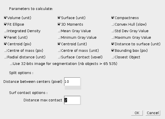
The Measure3D button will compute geometrical measurements on the selected objects, if no objects are selected, the measurements will be done for all objects. The various available measurements are available in the 3DManager options (Settings icon). The results table will show, you can then move the columns, or sort the rows based on a column. You can then save the values, and display the objects corresponding to the selected rows.
- Volume : the volume of the 3D object in calibrated unit, i. e. the number of voxels multiplied by the calibrated volume of one voxel. The raw volume (uncalibrated) is also displayed.
- Surface : the uncalibrated surface, i. e. the number of contour voxels. The calibrated surface is also computed taking into account all the faces of the contour voxel, for example a contour at the bottom of the object faces the X-Y plane, and a contour voxel at the side will face the X-Z or Y-Z plane.
- Compactness : this is the normalized ratio between the surface and the volume (see wikipedia). It should close to value 1 for spheres. Sphericity is the cube root of compactness. Different methods are proposed : using calibrated values or not, and a algorithm for computing compactness on discrete shape by Bribiesca (Pattern Recognition, 2008). Finally the algorithm from Lindblad (Image and Vision Computing, 2005) is implemented as a method to compute corrected surface in discrete spaces.
- Fit Ellipse : a 3D ellipsoid is fitted to the object. The values displayed are : major radius, ration between major and second radius, ratio between second and third radius, calibrated volume of the ellipsoid, ratio between volume of ellipsoid and volume of object.
- 3D Moments : shape descriptors based on order 2 moments.
- Feret : the largest calibrated distance between two contour voxels.
- Centroid : the coordinate of the geometrical centroid of the object, either in calibrated unit of uncalibrated voxel unit.
- Distance to surface : statistics about distances between the object centre and the contour voxels, average, minimum, maximum and standard deviation values.
- Bounding Box : the 6 coordinates of the bounding box in uncalibratd unit. Also displayed is the volume of this bounding box and the ration between the bounding box volume and the object volume.
- Convex Hull (experimental and slow !) : computes the 3D mesh of the object and the 3D convex hull of the object. The calibrated mesh surfaces are displayed for raw, smoothed and convex hull meshes. The calibrated volume of the 3D convex hull object is also computed. See 3D Shape for details.
Intensity measurements
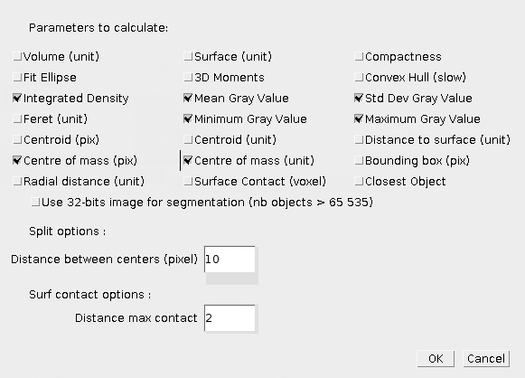
The Quantif3D button will compute intensity measurements on the selected objects, using active image. If no objects are selected, the measurements will be done for all objects. The various available measurements are available in the 3DManager options (Settings icon). The list of voxels with their intensity is available by clicking List Voxels. The results table will show, you can then move the columns, or sort the rows based on a column. You can then save the values, and display the objects corresponding to the selected rows.
- Integrated density : this is the sum of all intensity values inside the object.
- Statistics : various statistics about intensities inside the object, average, minimum, maximum and standard deviation.
- Centre of mass : intensity centre of the object, coordinates are weighted by their intensity value.
Distances and co-localisation analysis
Various distances measurements between two objects are available clicking the Distances button. If more than two objects are selected, all pairs will be processed. The label in the results table will display the processed pair. Note that two lines are used for one pair since some measurements are not symmetrical. The results table will show, you can then move the columns, or sort the rows based on a column. You can then save the values, and display the objects corresponding to the selected rows.
- Distances : The centre to centre distance (cen-cen) is available. The smallest distance between two objects is available as the distance between the two borders (bor-bor). The asymmetrical distance between centre of first object to border of second object is also computed (cen-bor).
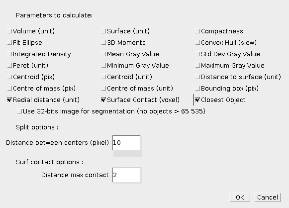
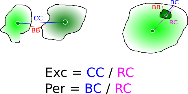
- Radial measurements : First calibrated radius of first object along direction between the centres of two objects is computed, this is the radiusCen measure. The eccentricity excen is the ratio between centre-centre (CC) distance and that radius (RC). You can also find the minimal border-border distance along the two centres to compute the periphericity as the ratio between the border-centre (BC) distance to the centre-centre distance (RC).
- Closest object : The closest object, either using centre-centre distance or border-border distance.
- Co-localisation and contact surface: Co-localisation measurements using the Colocalization button. This will compute the co-localised voxels (both in object1 and object2) as a percentage of volume of co-localised voxels to the object volume. The contact surface is also computed, i. e. the number of border voxels that are close to border voxels of the other object. The threshold for maximum distance for border voxels can be set up in Settings. A negative contact surface can be computed as number of border voxels of object1 that are inside object2. Total contact surface is simply the sum of negative and positive contact surface.
3D angle measurement
The angles are measured in 3D for three selected objects. The results will appear in the Log Window, three angles are computed in degrees, with each object the central object of the sector.
Drawing selected objects
Selected objects can be draw in the current image stack using the Fill Stack button. This will all the voxels of the object in the current colour in the color picker. Note that the stack must be in RGB mode in order to obtain coloured objects.
The objects can also be displayed in 3D using the 3D Viewer plugin. The current colour will also be used.
Macro extensions
All buttons and operations can be recorded, however we recommend you to first have a look to the Macro Functions available for 3DManager.


